Equipment
The light source needs to provide contrast with incident light reflected from the object, but not saturate the camera. To get good contrast, assuming we can avoid direct sunlight, a fluorescent tube illuminating a square with sides equal to the tube length is about right. A quick check is to point a photographic exposure meter or SLR camera at the source, with 100ASA film speed selected you want to get f/16 at 1/60s or equivalent.
The light level will inevitably vary across the box. The system will cope with quite a lot of variation, at the expense of tolerance to incident light. The light level in the darkest areas should not be less than 1/4 of the brightest (-2 stops).
Most cameras will cope with this light level, but only if they use a short exposure time, and with fluorescent lights that leads to flicker. There are three solutions.
- Use a lower illumination level and work the equipment in a shaded room. Provision of shade may be inconvenient and it may be hard to obtain adequate diffusion of the light because of the relatively high luminosity of the tubes.
- Use high frequency ballasts for the fluorescent tubes. This will totally eliminate flicker but may still put the camera close to its exposure limit.
- Use a filter to reduce the light level. An attenuation factor of 16 (four stops in photographic terms) is adequate. A piece cut from a pair of dark sunglasses placed in front of the camera will work if a little loss of resolution is acceptable.
The camera must be rigidly mounted facing the light table, a good distance above it. It should be normal (perpendicular) to the centre of the table. The distance depends on the specific camera but will be typically about twice the longest dimension of the illuminated area. Some adjustment of the camera should be provided for alignment, but it must be securely clamped against any vibration as movement of the camera will require background recalibration.
The camera must be capable of being set to manual exposure mode and producing uncompressed images in 16 or 24 bit colour depth. Most are, but it is a good idea to check that the settings are retained when the computer is switched off. It should have manual focus adjustment.
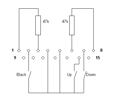
The software can be operated by keyboard, mouse or through the 'game' port. This last allows industrial controls to be attached, avoiding the risk of damage to (or theft of!) mouse or keyboard in a production environment. Three normally open push-button switches are be wired from the joystick button terminals (2, 7, 14) to ground (4,5). Wire two 47k resistors from the two analogue inputs(3,6) to +5V(1, 8) to enable Windows to recognise the device.
The software assumes a three button control panel with a large black button wired as button one ( the trigger) and buttons marked with up and down arrows wired as buttons two and four respectively.
Joystick Port Connections

| 1 | +5v | 6 | Analog 2 |
| 2 | Black Button (1) | 7 | Down Button (2) |
| 3 | Analog 1 | 8 | +5v |
| 4 | Ground | 10 | Button 3 (spare) |
| 5 | Ground | 14 | Up Button (4) |
